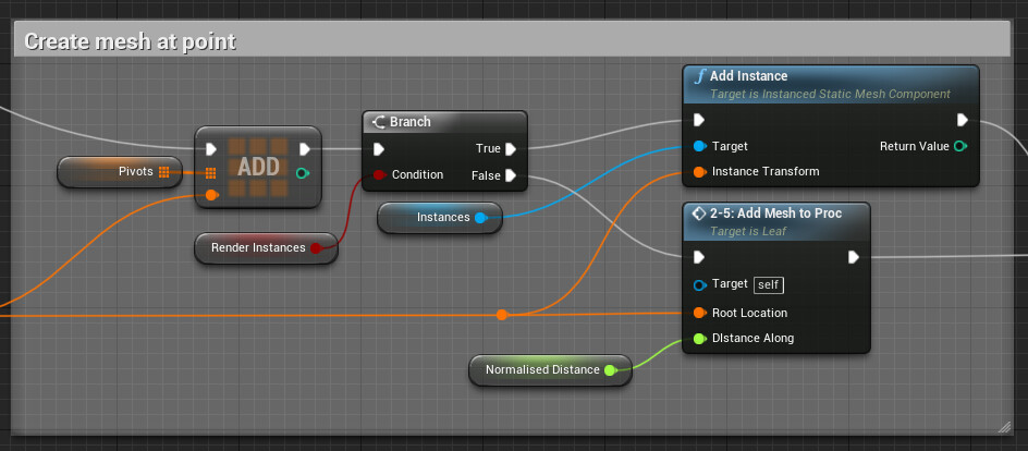
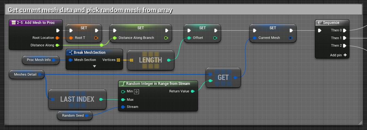
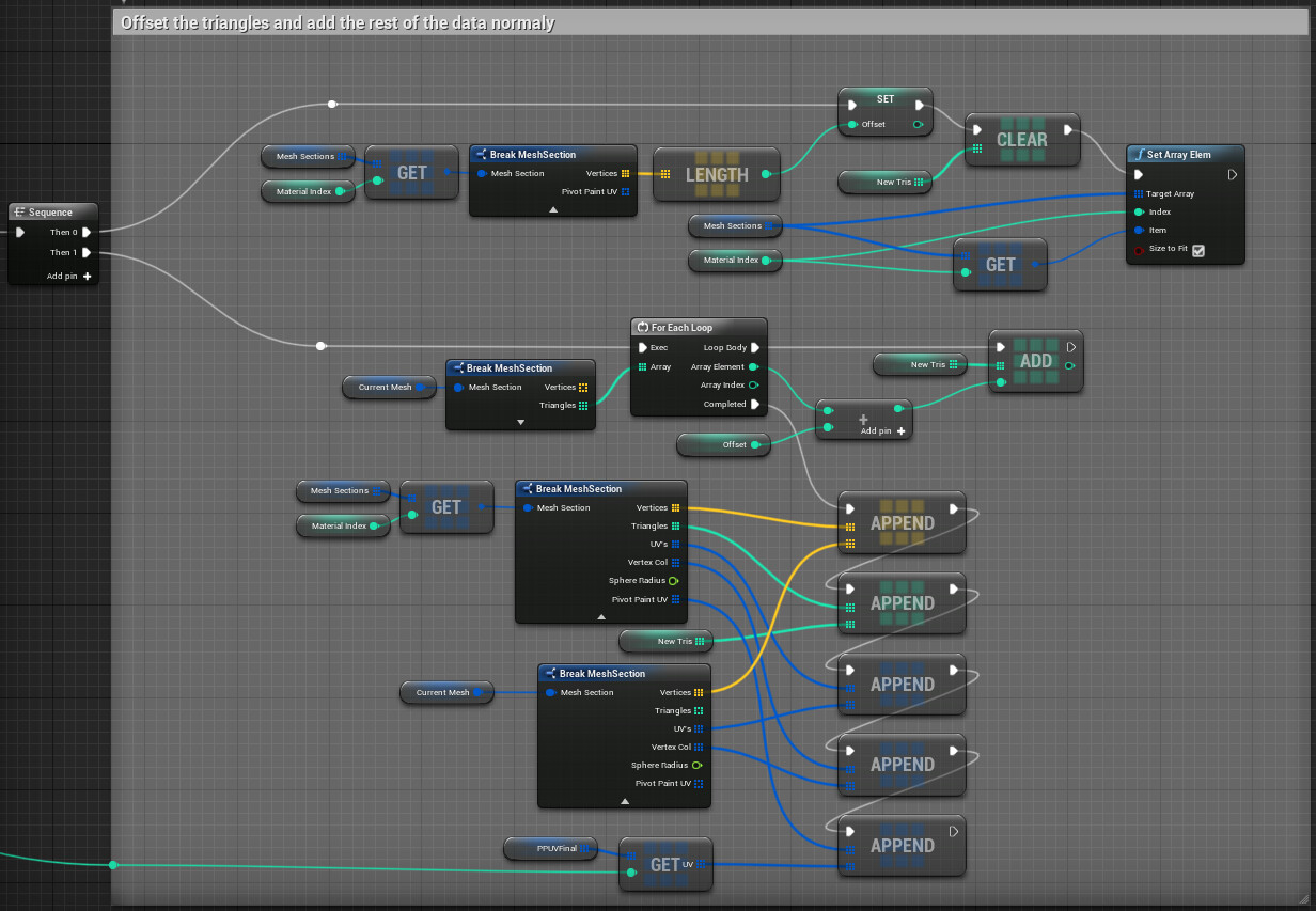
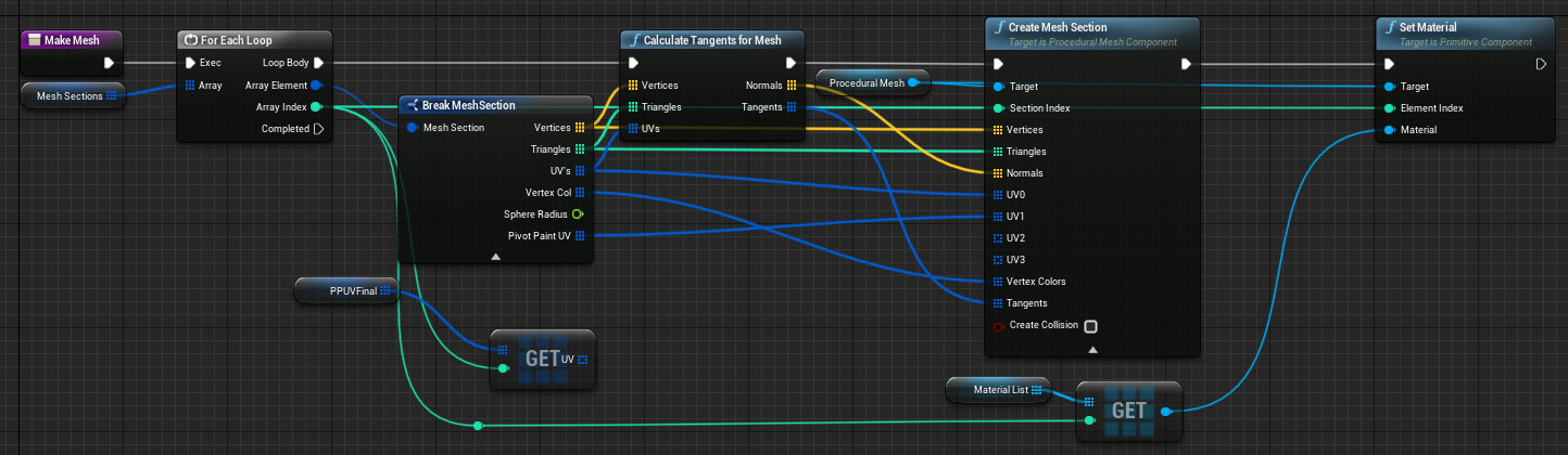
Before we dig into the creation of the foliage tool, I highly recommend downloading it and having a play around, some of the topics we will discuss will be quite abstract without it! You may also notice some references to pivot painter that aren’t covered. This is an extra feature I’m currently working on and is not yet done!
The foliage tool is broken into five separate blueprints;
-
Tree Parent
Holds data that will be shared across all children.
Trunk, Branch and Leaf blueprints inherit from it.
-
Trunk
-
Branch
Inherits from TreeParent
Spawns a number of branches, either along a surface or randomly
User control limited to a random variable range
Can be layered on top of one another
-
Leaf
-
Composite
You may be thinking, why do it this way!? Well, breaking the tree up has multiple benefits;
Don’t have to redraw the entire mesh when you make a change up the hierarchy
quickly separate and hide elements of the asset
Delete sections without ruining the whole tree
Assets become componentized, so you can copy and paste bits of a tree onto other trees
Splits the random seed generation so you get more control
All these elements come together to let the user build a modular stack of components that “should” allow them to make any kind of tree they want!
Base Parent
To save having to repeat work we should start by creating a base parent that our other blueprints will inherit from. This is useful because any data we put in the parent will be shared across its children. For example, every asset type will need a material reference and a set of arrays for the mesh, so that information should be added to the parent so it propagates to its children.
Add a procedural mesh component to the ‘TreeParent’ blueprint.
We also need a number of variables that will be needed across every child.
Base
Material, material to apply to the generated mesh, this does mean we only support one material per component.
ProcMesh, a struct containing the arrays required to make a mesh, Vertex, Triangle, UV and Vertex Colour. Normals are generated after with function.
Random Seed, randomise parts of the mesh
References
Parent, TreeParent variable used to reference its owner
Root, references the mesh composite tool, useful for getting stored order
Child Refs, array of treeparent types, used to tell objects parented to it to update.
T’s, an array of transform arrays, used to store the branch information. Think of it as the skeleton of the tree. Parented components reference this to get spawn location.
A shared function that tells the assets in the children array to update. This will get called every time a component is changed (though remember, these functions or casts won’t exist until we make them)
If we don’t update the child components, then the tree will quickly become disconnected.
Trunk
The trunk blueprint should inherit from TreeParent and is based on an editable spline which allows for a large amount of control. This can be added to any blueprint by selecting spline from the add component drop-down, just like we did with the procedural mesh component. You can see the components we have already inherited from as well.
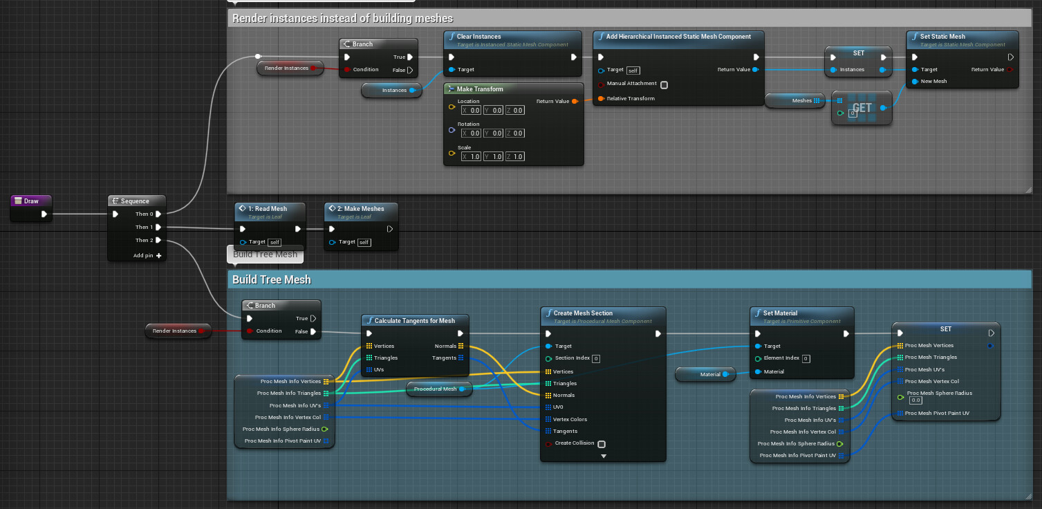
In the construction script, we add a new function called Draw. This is the function we call across itself and all its children.
The draw function checks to see if a parent trunk already exists, if it does, move the component along the parent spline. If a parent doesn’t exist, move straight along to create the mesh. Finally, tell the objects children to update with ‘Update Children’.
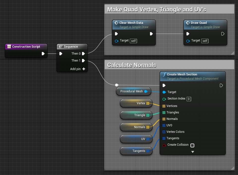
In ‘Create Base Segments’, we clear the old geometry data as we did in part 1, calculate new data, and then redraw the mesh. This will be the main pattern we do across all the components.
For our geometry, we need two integers, one for the number of length segments and one for the number of radial segments.
Get the length of the spline and number of length segments we want, divide them to get the distance between each point and set that to a float called Segment distance.
Then loop for each length segment and get the transform at distance along the spline. The length will be the current loop index * the segment distance. You can use scale x or y to control the thickness of the trunk. Multiply it by an exposed value to add a uniform size to the mesh.
You may need to Swivel the rotation here to line it up with the branch's rotation.
Store the transform in an array, this is really important as we need a generic way of knowing where the branches are in space, and not every blueprint will have a spline component. This will get added to Ts array (created in TreeParent) later on.
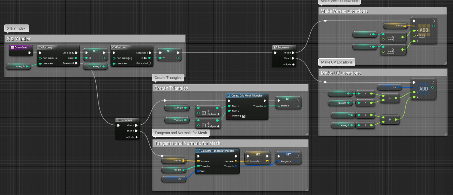
Then we draw the vertices around that transform in the Draw Radius Function. This is similar to how we drew geometry before. Click on the link to see the full graph.
https://blueprintue.com/blueprint/w1wqyfhj/
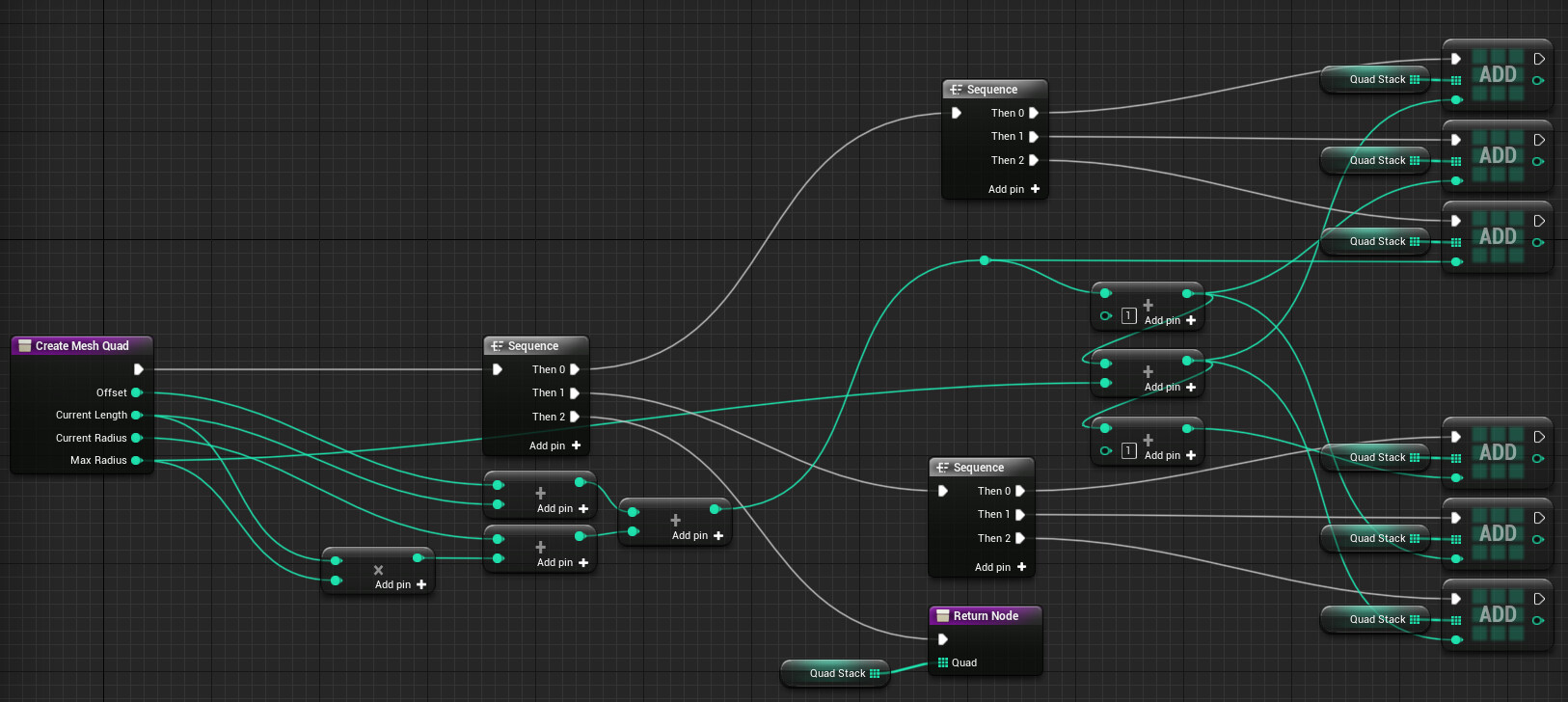
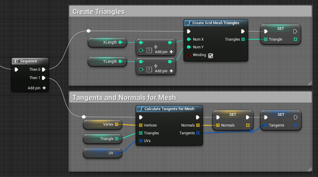
The only major difference here is the way we make the triangle array. This is kind of unnecessary for the trunk but is absolutely vital for making multiple branches work. The grid mesh triangles function is only expecting there to be a single mesh, but if we want to make multiple separate meshes, we need to offset our triangle counter.
Once all that is done, we need to take that base transform array we have been building and set it to the Ts array. The index here represents multiple branches but as we are only creating one segment this just gets set to index 0.
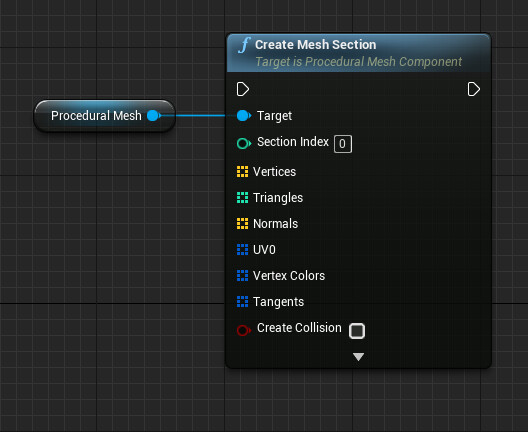
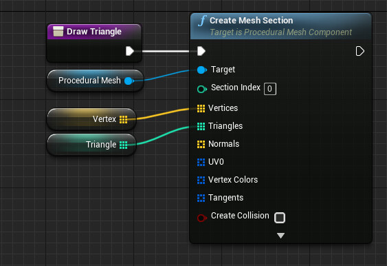
Once we have all the data, all that is left is to draw the mesh!
Branch
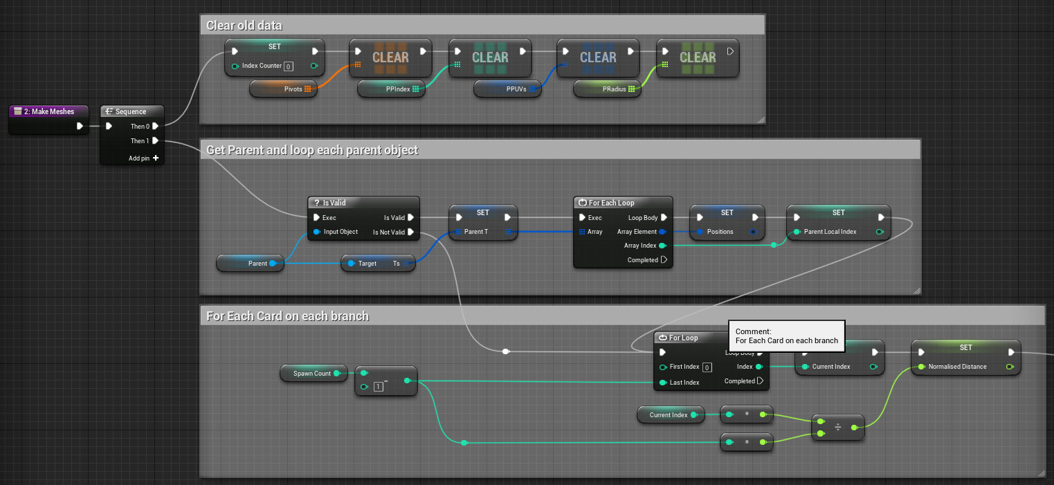
Hopefully, you are recognising a pattern by now, clear the old data and make new data. The branch blueprint needs to take in a parent (if one exists) and scatters multiple branches along it. If the parent doesn’t exist we just scatter them on the ground.
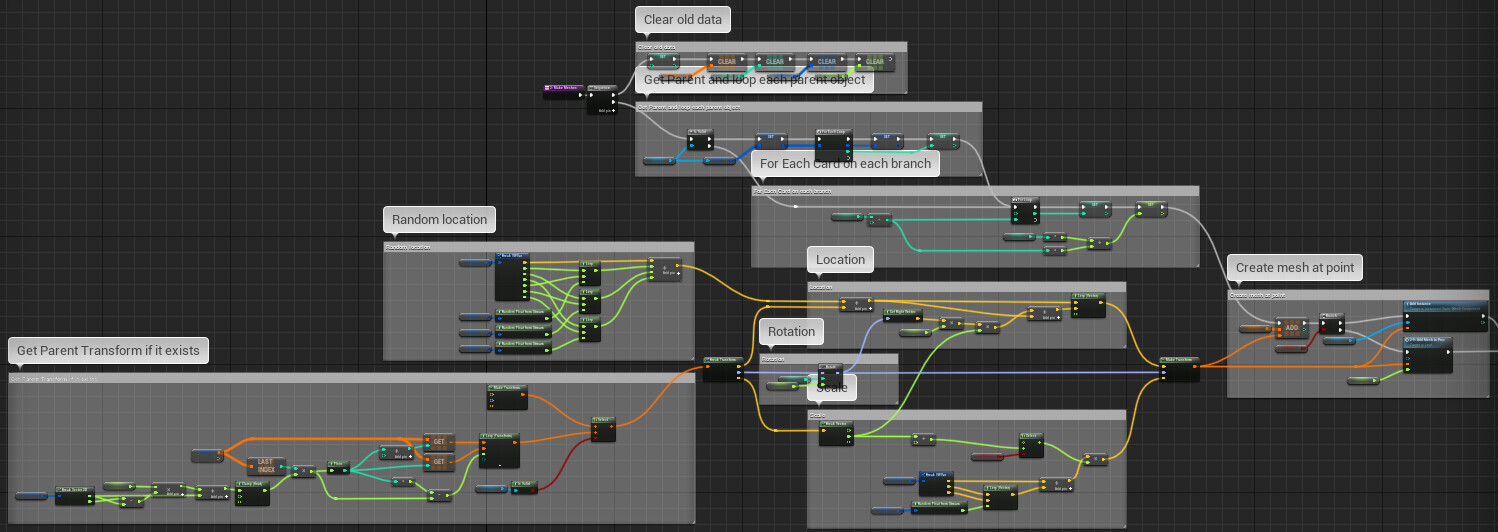
Nothing new in clear data, so let’s move on to ‘Make Branch Data’ The bulk of this function is finding the spawn point for each branch we are creating.
https://blueprintue.com/blueprint/je1omfbj/
Start off by figuring out if the blueprint has a parent or not. If it does, we get the parent’s T’s array, this is an array of transform arrays. Each branch is a new array of transforms. This means that if the parent branch has 8 branches and we choose to make 4 branches, it makes a total of 32 branches. If the parent is a trunk, the T’s array will only have one entry of transforms.
If it doesn’t have a parent, carry on and loop for branch count and figure out normalised distance.
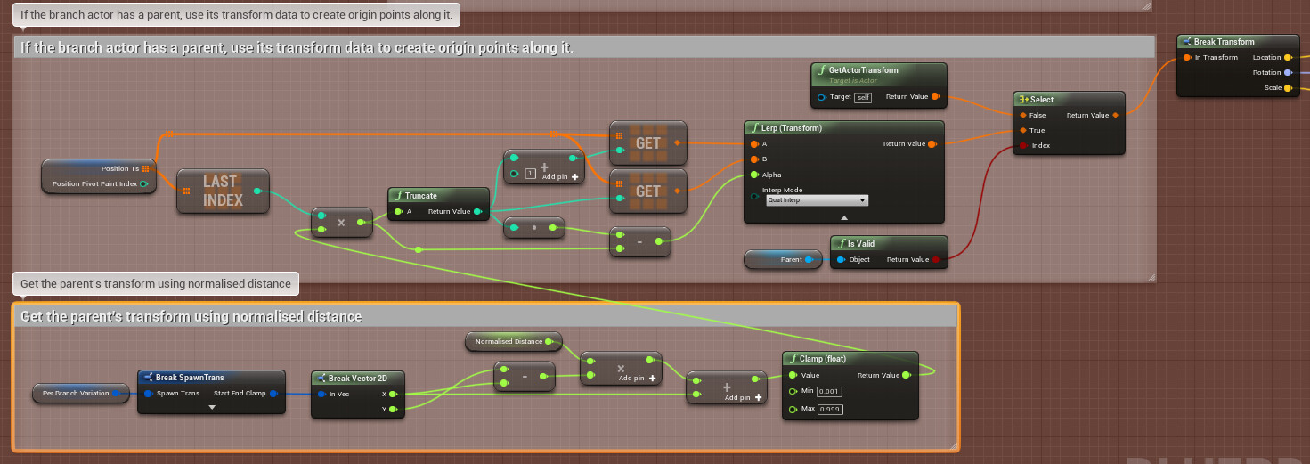
The next step is figuring out what each branch's origin should be. If there is no parent, just get the object's origin. If there is a parent, get the current transform array and find the location based on normalised distance. You can also add a clamp value here to shrink the range down
Here is a diagram to explain it a bit better if that sounded confusing. In the diagram below, the top value is normalised distance which needs to be translated to the array of transforms. Multiplying by transform index count gives us the nearest index and the remainder is the distance between the next index. This calculation will give us a rough distance along the transform length.
Generate a random location between a min and max vector.
Combine the location, modify rotation with a custom macro and modify the scale.
Sorting out origin rotation is a really important element, the macro, takes in data, like rotation along parent, rotation per index etc...To get easily controllable results, use rotate about index and use the direction vectors to avoid gimbal locking.
https://blueprintue.com/blueprint/w5hbxw70/
Once we have the origin, add it to a pivot array and create the branch.
In the trunk example, we used the spline to get a transform and then built geometry around it. We can’t do that here as the spline doesn’t exist. Instead, we have to generate those points.
https://blueprintue.com/blueprint/m4f5e-1h/
Take the origin point
Grab the current vert length. We need this to offset our triangle count. The Triangle array is just referencing an index on the vertex array so the offset is needed to keep the triangle reference correct. Generate a random branch length between a min/max.
Then for each point along the branch
Figure out the location of the next point. Take in the last transform, offset it by multiplying by a direction vector. Adjust it slightly with some controlled rotation.
Create mesh data, again, the same as we did before.
The important feature of the branch blueprint is that it is stackable. We should be able to build branches on branches on branches etc…
The only problem we may run into is that our branch count is exponential. If there are 6 branches in the first layer and 4 in the 2nd and 3rd, we would get 96 branches not 14. If we add a 4th layer of 4 branches, we get 384. The entire operation is using loops which means that we will get a lot of hitching if the numbers get to big
“Eventually I want to move over to an iterative editor tick to reduce this, along with a preview mode while editing values”