One of the best parts of Unreal is its accessibility for those who are more artistically inclined. With the initial release of Unreal Engine 4, people found (, myself included,) that they could make entire games without having to touch a line of C++. Since then, people have been pushing the limits of what blueprint can do and Epic has responded by expanding the toolset with each new update. An incredibly powerful part of this is the procedural mesh component, which takes in arrays of data and outputs a static mesh.
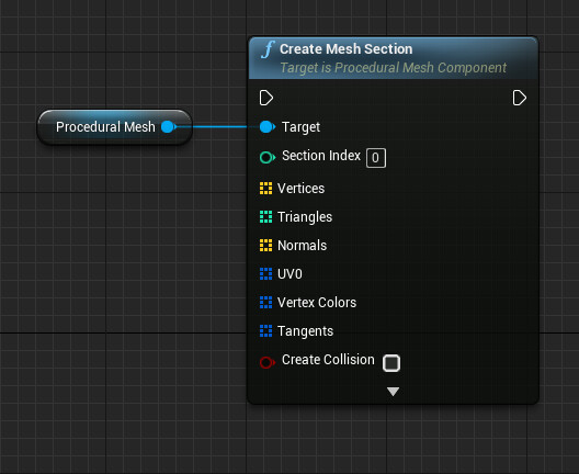
Combine this with the render to texture function and you can procedurally create Textured assets entirely in the engine!
Why is this useful?
You can see exactly what the asset will look like as your building it.
You can see the asset in its environment as your building it.
Updates are all in realtime.
There are tonnes of potential applications for this, and one I have been investigating is stylised foliage generation. Traditionally a pain in the backside to do with traditional modelling tools, the procedural mesh component is a great fit, as a game tree consists mostly of simple shapes (cylinders and planes) and is more about the correct placement and slight variation of those shapes rather than their individual complexity.
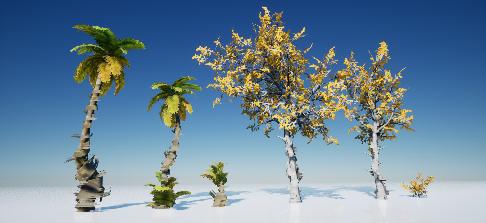
A selection of trees built using the procedural mesh component.
If you would like to try out the toolset I have made, you can download it here for free.
Check out the Trello board for a list of upcoming features and tutorials.
https://trello.com/b/HEBwnmYo/tree-tool
If you are inspired to make anything (Tree or Other) after reading this, I would love to see it! Share it with me on twitter
@ArranLangmead
Creating Basic Geometry
Creating a triangle
Let’s start off really simple and render a triangle. Create a new actor blueprint and add a procedural mesh component. Create a new function called draw triangle and plug it into the construction script.
Add two arrays;
An array of Vectors, these are our vertices
An array of integers, the target index of the vertex array
Here we have three vertices that represent the points of our triangle and the integer-order required to create that triangle. Note the order we need to list the vertices, if stored 0, 1, 2 the triangle will face the wrong way.

Add a ‘Create Mesh Section' function from the procedural mesh component reference and plug the arrays into their respective inputs.
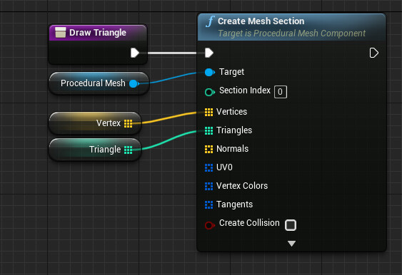
Hey presto! We just made a triangle!

Creating a plane
Now let’s get a bit more complex and make a plane. First off, we need to add some more arrays. We need to add;
Normals, an array of vectors (0,0,0)
Tangents, an array of struct vector + boolean (0,0,0 + 0/1)
UV’s, an array of 2d vectors (0,0)

But don’t worry, we are going to cheat to get our normals and tangents!
Remember, just like before, we need to clear our old array data.

Make a new function called Draw Quad and add two nested loops (cringe!). These will be our x and y grid count.

Take the current x and y values, multiply them by value (distance) and add that to the vector array. For UV’s, divide the current x and y value by its total (Length) to get a normalized value.

Use the ‘Create Grid Mesh Triangles’ function to automatically generate our triangle count. (We, unfortunately, won’t be able to use this later on, but for now, its an easy way to generate a grid of triangle data.
We also need our normals and tangents, so we can cheat again and use the ‘Calculate Tangents for Mesh’ function to get those.
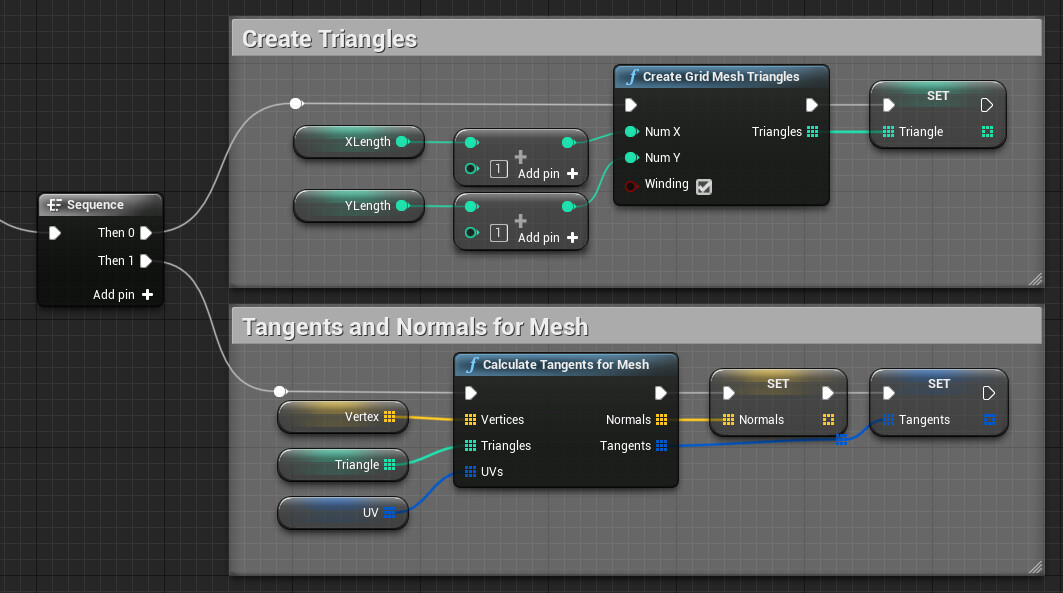
Here is the final function, use the link below to see a dynamic view.
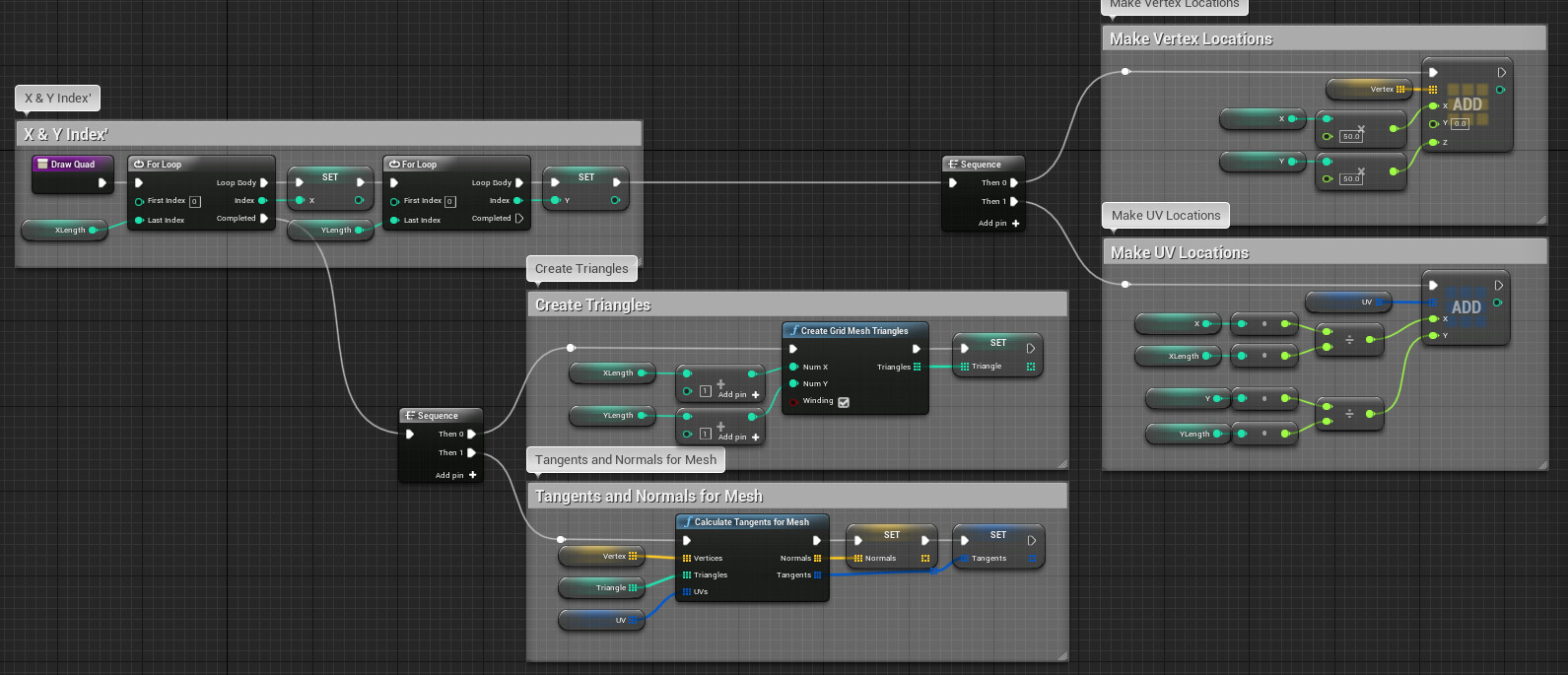
https://blueprintue.com/blueprint/5ewfbzzm/
Here's the construction script and final result.
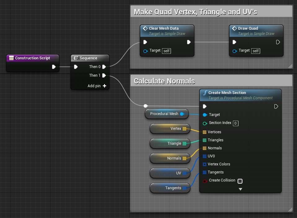

Creating a cylinder
Once we have a grid, it’s a simple matter to change the shape from a plane to a cylinder. Instead of aligning our verts to a grid, we wrap them around an axis.
Take that X and XLength value we created earlier, divide them to get a normalized value and then multiply by 360 giving us our angle. We want to rotate the x-axis around the z-axis so get those values and plug them in and * by float to control distance.

Swap this new calculation with the original x*float like so. Link below. Now our plane is a cylinder!

https://blueprintue.com/blueprint/sny4uty1/

And if we take the normalized height value and reverse it with a 1-x that creates a cone!

See where we’re going with this yet?

Reading a mesh
The last element we need is a mesh read. The ‘Get Section from Static Mesh’ function can grab the data from any mesh and output it for us to use. Now we can sample any mesh we like, modify it and then scatter it on or along a surface.

We now have everything we need to start building our own procedural content. In the next part, we will go over some of the unique quirks of applying these tools to making a simple tree generator.